
Views: 0 Author: Site Editor Publish Time: 2026-11-02 Origin: Site


Valve leakage drains operational efficiency across processing facilities. It causes measurable fluid loss, introduces severe environmental compliance risks, and forces unplanned downtime that halts production. Engineers rely on a stainless steel ball valve for rugged durability in harsh environments. However, premature failure often stems from misapplication, improper torque, or abrasive media rather than the metal itself. When a valve fails, maintenance teams must decide quickly between executing repairs or undertaking complete replacements. Making the wrong choice leads to recurring failures. This article provides a technical framework for diagnosing the exact source of a leak. You will learn how to execute immediate fixes and evaluate replacement options based on specific valve designs and application demands. We cover everything from stem packing adjustments to material selection.
Identify the Leak Source: Differentiate immediately between internal leakage (valve passing fluid when closed due to seat damage) and external leakage (fluid escaping from the stem-body junction or body joints).
Repair vs. Replace Threshold: Understand that repairability is dictated by design; a 1-piece valve is typically replaced, whereas multi-piece configurations allow for seat and seal rebuilds.
Root Cause Mitigation: Recognize that tightening a packing nut is a temporary fix if the underlying issue is abrasive debris ingress, thermal cycling, or chemical incompatibility.
Supplier Evaluation: Selecting the right replacement requires scrutinizing material test reports (MTRs), factory pressure testing protocols, and pressure-temperature ratings, not just unit cost.
Defining acceptable leakage rates requires referencing established industry standards. Organizations use frameworks like API 598 or FCI 70-2 to determine success criteria. Zero leakage serves as a functional target rather than an absolute physical reality. Achieving this target depends heavily on the seal material and the pressure class of the system. Soft-seated valves generally provide tighter shut-offs compared to metal-seated variants. Understanding the mechanical pathways of fluid escape helps operators isolate problems quickly. We look at two primary failure paths: internal passing and external boundary leaks.
Internal leakage occurs when the ball fails to seal against the upstream or downstream seats. Fluid bypasses the closure mechanism even when the handle indicates a fully closed position. Most standard designs utilize a floating ball concept. Fluid pressure pushes the unattached ball downstream. This physical displacement forces the ball into the downstream seat, creating a tight mechanical seal.
Low-pressure applications sometimes fail to energize the seat seal adequately. Without sufficient line pressure, the ball does not compress against the PTFE or RTFE material. This lack of compression allows fluid to seep through the microscopic gaps. Seat wear exacerbates this phenomenon. Repeated cycling degrades the soft seat material over time. Once the seat profile loses its original geometry, internal passing becomes inevitable. Operators often misdiagnose this as a faulty valve when the actual issue is insufficient system pressure to create the seal.
External leakage presents a more visible hazard. Fluid escapes into the surrounding environment, creating safety and compliance issues. The stem packing assembly remains the most common source of external leaks. This assembly typically includes a gland nut, a thrust washer, and several packing rings. Dynamic movement occurs every time an operator turns the handle. This rotational friction leads to gradual wear at the stem-body junction. The packing material compresses and loses its elasticity, creating a pathway for fluid to escape.
Body joint leaks occur primarily in multi-piece valves. These designs rely on body gaskets and secure bolting to maintain pressure boundaries. Compromised body gaskets fail under thermal stress or chemical attack. Uneven bolt torque during assembly or maintenance creates uneven compression on the seals. Fluid finds the path of least resistance through these unevenly compressed zones. Vibration from nearby pumps or compressors can also loosen body bolts over time, initiating unexpected external leaks.
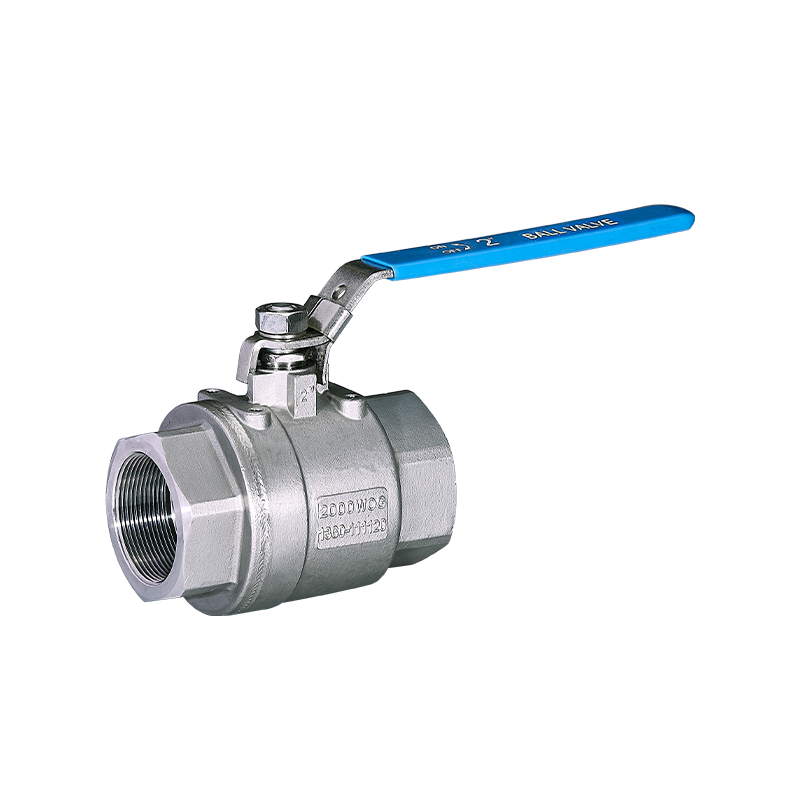
Evaluating an industrial stainless steel ball valve requires looking at physical and operational realities. Various factors degrade valve integrity over time. Identifying these root causes prevents recurring failures and extends operational lifespans. We break down the physical and operational realities that destroy valve seals.
Pipelines rarely transport perfectly clean media. Particulate matter frequently travels through the system. Scale, weld slag, and sand get trapped between the rotating ball and the soft seats. When an operator closes the valve, these hard particles grind into the PTFE or RTFE material. This grinding action creates deep grooves in the seats. Newly constructed pipelines often contain residual weld slag. If operators fail to flush the lines before cycling the valves, this slag immediately destroys the PTFE seats. Similarly, well water applications frequently pump fine sand. This sand embeds itself into the soft seats, turning them into abrasive pads that slowly grind away the stainless steel ball.
More severe damage occurs when debris causes permanent scoring of the stainless steel ball itself. The highly polished surface of the ball becomes scratched and pitted. A scored ball acts like a file against the soft seats. Installing new seats against a damaged ball proves futile. The rough surface will immediately destroy the new seals during the first few cycles. Filtration and proper pipeline flushing remain mandatory for preventing this specific failure mode.
High-cycle operations place immense stress on the stem packing. Automated valves actuating hundreds of times a day experience rapid packing degradation. Thermal cycling adds another layer of complexity. Systems fluctuating between hot and cold states cause metal components to expand and contract. This continuous dimensional shifting causes gland nuts to loosen during operation. A loose gland nut fails to compress the packing rings, leading directly to stem leaks.
Incorrect initial torque creates immediate operational hazards. Under-torquing at the factory or during routine maintenance leaves the packing loose. This guarantees immediate leakage upon system pressurization. Conversely, over-torquing crushes the packing material. Crushed packing loses its ability to flex and seal dynamically. Excessive torque also dramatically increases the operating friction. Operators must exert more force to turn the handle, which can eventually bend or snap the valve stem. Maintenance personnel should always use a calibrated torque wrench when adjusting packing nuts, following the manufacturer's specific torque values. Relying on feel often results in over-tightening. Automated valves require live-loaded packing systems. These systems use Belleville washers to maintain constant tension on the packing, compensating for wear and thermal expansion automatically.
A widespread misconception assumes stainless steel is immune to all forms of corrosion. While highly resistant, grades like 304 and 316 remain vulnerable to specific chemical attacks. Chlorides present in saltwater or cleaning agents cause pitting and stress corrosion cracking. Galvanic corrosion occurs when dissimilar metals connect within the piping system without proper isolation. Incompatible aggressive media will slowly dissolve the internal components. For instance, 304 stainless steel degrades rapidly when exposed to high concentrations of sodium hypochlorite. Upgrading to 316 stainless steel provides better resistance due to the addition of molybdenum, but even 316 has limits in highly acidic environments like concentrated sulfuric acid. Engineers must consult chemical compatibility charts before specifying valve materials.
Mineral scaling presents a different mechanical challenge. Hard water or specific chemical processes deposit minerals on the ball surface. This scaling restricts the ball's movement. Operators find it impossible to achieve a full 90-degree closure. The valve remains partially open, allowing continuous internal leakage. External environmental factors also degrade exterior components. Coastal air introduces continuous salt exposure. Harsh washdown chemicals in food processing facilities degrade the stem-body junction over time, weakening external seals.
Installation errors compromise valve integrity before the system even goes live. Overtightening threaded connections forces the valve body out of alignment. Welding a valve into a pipeline without proper heat dissipation warps the internal cavity and melts the soft seats. Failing to support heavy piping transfers mechanical stress directly onto the valve body, causing joint separation. Pipe misalignment is a frequent culprit. Forcing a valve between two misaligned pipe flanges places immense bending stress on the valve body. This stress distorts the internal cavity, causing the ball to bind against the seats. It also compromises the body joint seals in multi-piece valves, leading to immediate external leakage.
Transportation practices frequently cause unseen damage. Lifting heavy valves by the handle or actuator bends the stem. A bent stem creates an elliptical rotation path, destroying the packing seal and guaranteeing immediate leakage. Factory defects also play a role. Failure to perform rigorous pre-installation testing results in installing valves that were already compromised before leaving the manufacturing facility. Visual inspections rarely catch microscopic porosity in cast bodies.
Addressing stainless steel ball valve leakage requires a step-by-step, evidence-based methodology. Randomly tightening bolts often worsens the problem. Maintenance teams must approach active leaks safely and systematically.
Stem leaks represent the most straightforward repair scenario. The procedure for safely tightening the packing nut requires precision. Follow these exact steps to address a leaking stem:
Verify the exact location of the leak is at the stem base, not the body joint.
Remove the handle retaining nut and lift the handle off the stem.
Locate the packing gland nut directly beneath the handle assembly.
Use a properly sized wrench to turn the nut clockwise in small, quarter-turn increments.
Wipe the area clean and observe if the fluid seepage stops.
Safety warnings must dictate this process. Never attempt major adjustments on a fully pressurized line. Depressurize the system if a quarter-turn does not stop the leak. Over-tightening increases operating torque significantly. If the nut requires excessive force, the packing material is likely degraded beyond repair. Forcing the nut further will damage the internal thrust washer and score the stem.
Internal passing requires a complete valve rebuild. Begin by isolating the valve using upstream and downstream block valves. Drain the trapped fluid safely. Remove the valve from the line and transfer it to a clean workbench. Disassemble the body components carefully, noting the orientation of the ball and seats.
Isolate the valve and verify zero pressure in the line.
Remove the valve from the piping system.
Unbolt the body sections and separate the end caps from the main body.
Extract the ball and inspect it for scoring or pitting.
Remove the old seats and body seals using a non-marring pick.
Clean the internal cavity thoroughly with an approved solvent.
Install the new seats, ensuring they sit flat in their machined pockets.
Reassemble the body, tightening the bolts in a star pattern to the specified torque.
Inspect the ball under bright light. Look for scratches, pitting, or mineral buildup. If the ball shows permanent scoring, a standard rebuild kit will not solve the problem. The economic viability of rebuilding depends on labor costs. Rebuild kits containing new seats, seals, and thrust washers cost a fraction of a new valve. However, the labor required to clean, inspect, and reassemble the unit often exceeds the price of a small replacement valve.
Never reinstall a rebuilt valve without proper validation. Hydrostatic or pneumatic bench testing ensures seal integrity. Connect the valve to a test rig and apply pressure according to API 598 guidelines. Check for internal passing by monitoring the downstream port. Check for external leaks by applying a soapy water solution around the stem and body joints. API 598 dictates specific hold times based on valve size. For a standard 2-inch valve, the hydrostatic shell test must hold pressure for at least 15 seconds without visible leakage. The seat test requires holding pressure and monitoring for drops. Skipping these hold times invalidates the test.
Bench testing prevents the costly mistake of installing a faulty valve back into a live system. It verifies that the new seats align correctly and that the packing nut holds pressure. Pre-installation validation should also apply to brand-new valves pulled from inventory. Factory defects happen, and catching them on a test bench saves hours of field labor.
Maintenance managers need a framework for decision-making based on valve size, pressure class, and downtime costs. A simple rule of thumb guides most industrial facilities: small, standard-port valves are cheaper to replace, while large, high-pressure, or actuated valves warrant rebuilding.
Valve Characteristic | Repair Recommendation | Replacement Recommendation |
|---|---|---|
Size & Port Configuration | Large diameter (over 2 inches), full-port designs | Small diameter (under 2 inches), standard or reduced port |
Body Construction Style | 2-piece or 3-piece bolted bodies designed for disassembly | 1-piece welded or tightly threaded throwaway bodies |
Application Pressure | High-pressure, extreme temperature, or critical process systems | Low-pressure utility lines (water, basic air) |
Actuation and Automation | Automated, pneumatically, or custom-actuated valves | Standard manual lever operation |
The initial architectural choice of the valve dictates future maintenance realities. Evaluating scalability and value influencing factors helps engineers specify the correct equipment during the design phase.
A 1-piece valve features a unified body construction. This design inherently reduces the port size, restricting flow slightly. Manufacturers typically weld these bodies shut or thread them together with high-strength adhesives. Internal repair proves virtually impossible. When the seats fail, operators treat them as throwaway valves. They offer low initial costs but zero repairability.
Contrast this with a 2 piece stainless steel ball valve. This design splits the body into two distinct sections bolted or threaded together. It offers a balance of full-port flow and maintenance accessibility. Technicians can disassemble the body to access the internal cavity. This allows for straightforward seat and seal replacements, extending the asset's lifecycle significantly.
Industrial pipelines frequently utilize a stainless steel flanged ball valve for maintenance advantages. Flanged connections allow for rapid drop-out and replacement. Technicians simply remove the flange bolts and slide the valve out of the pipeline. This eliminates the need to cut pipe or unthread tight connections in confined spaces.
However, flanged designs introduce specific leak risks at the flange faces. Gasket failure between the valve and the pipe flange causes external leakage. Improper bolt sequencing during installation creates uneven pressure on the gasket. Technicians must follow a star-pattern tightening sequence and use a calibrated torque wrench to ensure uniform compression across the flange face.
Material manufacturing methods impact pressure retention capabilities. Cast bodies involve pouring molten metal into molds. This process occasionally leaves microscopic voids or porosity within the metal structure. Under extreme pressure, gas or fluid can migrate through these porous pathways, causing body leaks.
A forged stainless steel ball valve eliminates the risk of porosity. Forging compresses solid metal under immense pressure, aligning the grain structure and creating a denser, stronger body. This manufacturing method proves superior for high-pressure hydraulic systems or critical gas applications. In these environments, body leaks result in catastrophic failures, making forged construction a mandatory safety requirement.
Vetting vendors prevents recurring failures and mitigates implementation risks. Buyers must look beyond initial purchase prices and evaluate the technical competence of their stainless steel ball valve supplier.
Counterfeit materials plague the industrial valve market. Buyers must demand Material Test Reports (MTRs) for every critical valve purchase. MTRs verify the exact chemical composition of the stainless steel. For example, ensuring 316SS actually contains the required molybdenum guarantees its resistance to chloride corrosion. Without MTRs, facilities risk installing inferior alloys that will fail prematurely. Advanced facilities go a step further by performing Positive Material Identification (PMI) testing upon receipt. PMI uses a handheld X-ray fluorescence analyzer to confirm the alloy composition on the loading dock. This prevents counterfeit valves from ever entering the inventory.
Testing protocols separate reliable suppliers from commodity brokers. Verify that the supplier adheres strictly to API 598 or ISO 5208 pressure testing standards before shipment. Factory testing eliminates out-of-box defects. Suppliers should provide testing certificates documenting the test pressures, hold times, and leakage acceptance criteria used during final inspection.
Partnering with a knowledgeable supplier ensures proper application matching. A competent vendor evaluates the media type, operating pressure, temperature extremes, and cycle frequency. They do not simply sell off-the-shelf commodities. They ask questions about fluid velocity and particulate content.
Standard PTFE seats fail in high-temperature or highly abrasive applications. Specialized seat materials provide necessary upgrades. PEEK offers superior temperature resistance. Delrin handles higher pressures without deforming. Metal-seated designs crush abrasive particles rather than allowing them to score soft seals. A quality supplier will guide engineers toward these specialized materials when process conditions demand them.
While stainless steel ball valves offer robust performance, they are not maintenance-free devices. Leakage serves as a symptom of mechanical wear, misapplication, environmental degradation, or improper installation. Understanding the mechanics of internal passing versus external stem leaks allows maintenance teams to respond effectively. The decision tree remains logical: tighten the packing for minor stem leaks, replace throwaway 1-piece valves, rebuild 2-piece or 3-piece valves if the ball remains un-scored, and upgrade to forged or flanged designs for demanding industrial environments.
Take the following steps to optimize your fluid control systems:
Audit your current leaking valves to identify the exact source of fluid loss.
Document failure modes and operating conditions for each compromised unit to spot recurring trends.
Depressurize lines and attempt incremental packing nut adjustments on active stem leaks.
Consult a qualified technical supplier to specify correct valve designs and specialized seal materials for your specific process conditions.
A: Leaks at the handle originate from the stem packing at the stem-body junction. Thermal cycling, incorrect initial torque, or high-cycle wear degrades the stem seal over time. The packing material loses its elasticity and fails to hold pressure. Tightening the packing nut slightly can often compress the seal and resolve the leak.
A: 1-piece designs are generally not repairable due to their unified body construction. Manufacturers weld or tightly thread these bodies together, preventing internal access. When the internal seats fail or the stem seal degrades beyond external adjustment, you must replace the entire unit.
A: Internal passing occurs due to damaged or worn seats. Abrasive debris like scale or sand gets trapped during closure, scoring the soft PTFE seals. In severe cases, the debris permanently scratches the stainless steel ball itself, preventing a tight mechanical seal against the seats.
A: Recommend cast valves for standard, low-to-medium pressure applications due to their cost efficiency. Choose forged valves for high-pressure, high-temperature, or critical gas systems. Forging eliminates material porosity and micro-cracks, ensuring the valve body will not leak under extreme operational stress.
A: Lifespan varies wildly based on application factors like media abrasiveness, cycle frequency, temperature, and environmental exposure. A baseline lifespan in clean water might reach 5 to 10 years. However, exposure to harsh chemicals, abrasive slurries, or improper torque can reduce this lifespan to mere months.
A: A 2 piece stainless steel ball valve must be fully removed from the pipeline to be disassembled and rebuilt. A 3 piece valve allows the center body section to swing out for rapid seat replacement while the end caps remain securely attached to the pipe, offering the easiest inline maintenance.


