
Views: 0 Author: Site Editor Publish Time: 2026-10-19 Origin: Site


Misinterpreting valve pressure ratings causes catastrophic system failures. It leads directly to fugitive emissions and unplanned downtime in industrial fluid control. Procurement and engineering teams often default to nominal pressure metrics like Cold Working Pressure. They ignore dynamic operational variables during the specification process. Temperature spikes, media corrosivity, and mechanical pipe stress change everything on the job site. This oversight consistently leads to under-specified or over-engineered valve selections.
Accurately decoding a high pressure ball valve rating requires deep technical understanding. You must analyze the interplay between ANSI classes, material limits, and Pressure-Temperature (P-T) curves. This guide provides a strict framework for evaluating these specifications. We ensure safe, compliant, and cost-effective procurement for your piping systems. By following these guidelines, you guarantee tighter shut-offs and endurance against extreme mechanical wear and tear.
P-T Curves Dictate True Capacity: A valve’s maximum pressure rating is not static; it inversely correlates with operating temperature and is strictly limited by the weakest component (typically the soft seats or seals).
Failure Modes Differ: Exceeding pressure limits can result in either mechanical failure (body rupture) or leakage (seat failure); understanding this distinction is vital for safety calculations.
Material Density Matters: Manufacturing methods directly impact pressure tolerance. Forged bodies offer superior structural integrity over cast bodies in high-stress, high-cycle applications.
Standardization is Critical: Relying on standardized metrics (ANSI/ASME B16.34, API 598, BS 5351) rather than generic manufacturer claims ensures verifiable performance and regulatory compliance.
Supplier Vetting Reduces Risk: Sourcing from a certified industrial high pressure ball valve supplier guarantees access to essential documentation, including Material Test Reports (MTRs) and hydrostatic testing data.
Engineers must translate system requirements into standardized valve rating nomenclature. You need the maximum allowable working pressure and the maximum design temperature. This translation ensures you specify the correct valve for the specific pipeline. Guesswork in this phase leads to immediate safety violations and rapid equipment degradation. Field technicians often see a valve fail not because of a manufacturing defect, but because the initial specification ignored transient pressure spikes during pump startups.
CWP stands for Cold Working Pressure. It represents the maximum pressure the valve withstands at ambient temperatures. This range typically spans -20°F to 100°F. When you see a high pressure ball valve pressure rating listed simply as a number, it usually refers to CWP. However, ambient conditions rarely reflect actual operating environments. A valve rated for 2000 CWP will not survive 2000 PSI at 300°F.
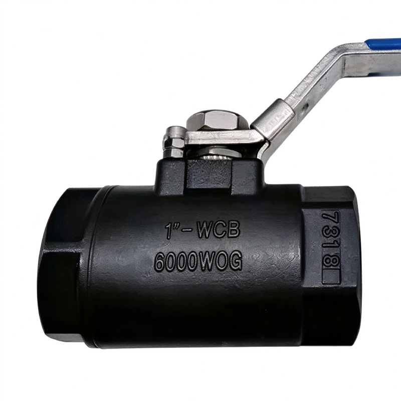
WOG means Water, Oil, and Gas. WSP stands for Working Steam Pressure. Historically, field technicians relied heavily on WOG and WSP to gauge valve limits. Modern engineering prefers CWP combined with specific P-T graphs. These graphs offer precise operational boundaries rather than generic fluid categories. PN stands for Pressure Nominal. It serves as the European standard equivalent to PSI and ANSI ratings. Converting PN to PSI is necessary for international projects. For example, PN40 roughly translates to a Class 300 rating, though exact material limits still apply.
Metric Acronym | Meaning | Primary Application | Limitations |
|---|---|---|---|
CWP | Cold Working Pressure | Standard ambient temperature lines | Does not account for thermal derating |
WOG | Water, Oil, Gas | Legacy plumbing and general industry | Outdated; lacks specific temperature data |
WSP | Working Steam Pressure | Boiler and steam distribution | Only applies to saturated steam conditions |
PN | Pressure Nominal | European DIN standard systems | Requires conversion for ASME piping |
The ASME B16.34 standard categorizes valves into distinct pressure classes. Common classes include 150, 300, 600, 900, 1500, and 2500. This standard dictates the minimum wall thickness and material requirements for each class. BS 5351 defines pressure and temperature rating graphs. It focuses specifically on steel ball valves used in petroleum and petrochemical industries. Adhering to these standards removes ambiguity from the procurement process.
A 300LB flanged ball valve does not mean it is limited to 300 PSI. Instead, it denotes a specific pressure-temperature matrix based on the body material. A Class 300 carbon steel valve handles over 740 PSI at room temperature. Dimensional standardizations accompany these classes. Flange thickness and bolt circles dictate drop-in replacements during maintenance. You cannot bolt a Class 600 valve to a Class 300 flange, regardless of the internal pressure. The bolt holes will not align, and the flange faces will not seal.
ASME B16.34 Class | Ambient Pressure Limit (Carbon Steel) | Hydrostatic Shell Test Pressure |
|---|---|---|
Class 150 | 285 PSI | 450 PSI |
Class 300 | 740 PSI | 1125 PSI |
Class 600 | 1480 PSI | 2225 PSI |
Class 900 | 2220 PSI | 3350 PSI |
Class 1500 | 3705 PSI | 5575 PSI |
A conceptual trade-off exists between high pressure handling and high temperature tolerance. As temperature rises, the tensile strength of the valve body decreases. The structural integrity of the internal seats also weakens significantly. You must account for both variables simultaneously. Ignoring this relationship guarantees a blowout.
Specifying a valve based solely on ambient pressure ratings introduces severe danger. Applications often involve thermal cycling or elevated continuous temperatures. Thermal expansion of media trapped in the valve cavity causes massive pressure spikes. When a closed valve heats up, the trapped fluid expands. Water expands roughly 4% when heated from freezing to boiling. In a confined rigid space like a valve cavity, this translates to thousands of PSI in pressure increase. These spikes easily exceed the CWP, destroying the internal components.
Exceeding the body's mechanical limits leads to catastrophic rupture. This releases dangerous media into the environment and endangers personnel. Exceeding the seat's limits leads to internal bypass leakage. The valve remains intact externally, but fluid passes downstream when closed. Differentiating between these failure modes is critical for system safety and maintenance planning.
To prevent cavity expansion failures, follow these field practices:
Install cavity relief holes on the upstream side of the ball to vent excess pressure back into the line.
Specify self-relieving seats that flex under excessive cavity pressure, allowing fluid to escape safely.
Implement external thermal relief valves on isolated pipe sections exposed to direct sunlight.
Monitor ambient temperature swings in exposed outdoor installations during seasonal changes.
Reading a manufacturer's P-T curve graph is mandatory for safe operation. Look for the "knee" in the curve. This point shows where pressure capacity drops precipitously as temperature increases. Below the knee, the valve handles near-maximum pressure. Above the knee, capacity plummets.
You must calculate the Maximum Allowable Working Pressure (MAWP). Always base this calculation on the maximum design temperature of your system, not the average operating temperature. If your system spikes to 400°F during cleaning cycles, you must derate the valve capacity based on that specific 400°F metric. A valve operating normally at 150°F will fail during that 400°F steam purge if you only specified for the lower temperature.
Soft parts dictate the actual operational limits of the valve. The metal body's strength matters less if the seats fail and melt. Standard PTFE handles moderate pressures up to roughly 400°F. It deforms under extreme pressure. Reinforced PTFE provides better resistance against deformation and wear by incorporating glass or carbon fibers.
PEEK is excellent for extreme high-pressure applications. It maintains structural integrity at higher temperatures and resists extrusion under heavy load. Metal-seated ball valves serve as the necessary alternative. Use them when both pressure and temperature exceed the limits of elastomeric or thermoplastic seals. Metal seats handle severe abrasives and temperatures exceeding 1000°F.
Seat Material | Max Temperature Limit | Pressure Handling Capability | Best Industrial Application |
|---|---|---|---|
Standard PTFE | ~400°F (204°C) | Moderate | General water, oil, and gas lines |
Reinforced PTFE (RTFE) | ~450°F (232°C) | High | Steam systems, moderate chemicals |
PEEK | ~500°F (260°C) | Extreme | High-pressure hydraulic systems |
Metal-to-Metal | 1000°F+ (537°C+) | Extreme | Severe abrasive media, extreme heat |
Selecting an incompatible material for the media or environment creates severe implementation risks. It leads to accelerated corrosion and wall thinning. Premature pressure boundary failure follows shortly after. Material selection dictates the baseline strength of the entire assembly.
A high pressure carbon steel ball valve is ideal for non-corrosive environments. Common grades include WCB for castings and A105 for forgings. They perform exceptionally well in oil and gas pipelines, hydraulic systems, and standard industrial fluid transfer. Carbon steel provides excellent tensile strength at a cost-effective price point.
Carbon steel has strict temperature limitations. It suffers from brittleness at very low temperatures, making it unsuitable for cryogenic applications. It also experiences strength loss at extremely high temperatures. You must apply protective coatings to prevent external rust in humid or coastal environments. Uncoated carbon steel degrades rapidly in salt-heavy air, compromising the pressure boundary from the outside in.
Compare the grain structure of forged steel and cast steel to understand pressure limits. Forged steel like A105N or F316 offers superior density. The forging process aligns the metal grain, eliminating internal voids. Cast steel like WCB or CF8M can contain microscopic flaws, porosity, and shrinkage cavities.
A forged steel ball valve remains the industry standard for extreme pressures. It dominates Class 900, 1500, and 2500 applications. The absence of porosity prevents leaks under high stress. When a system undergoes rapid pressure cycling, forged bodies resist fatigue failure far better than their cast counterparts. We always specify forged bodies for main isolation points on high-pressure injection skids.
Engineers use 316 and 316L stainless steel for corrosive high-pressure media. The added molybdenum increases resistance to pitting and crevice corrosion. This makes it suitable for chemical processing and mild offshore environments. However, standard stainless steel is not enough for the most aggressive fluids.
Escalate to Duplex, Super Duplex, or Inconel for harsher environments. These alloys handle offshore platforms and sour gas applications effortlessly. They ensure strict NACE MR0175 compliance in highly acidic conditions containing hydrogen sulfide. The standard requires material hardness to remain below HRC 22 to prevent sulfide stress cracking. While expensive, these exotic alloys prevent catastrophic failure under high pressure. A failed valve on an offshore rig costs infinitely more than upgrading to Super Duplex during the design phase.
Matching specific valve designs to standard industrial pressure tiers ensures reliability. You cannot use a general-purpose valve in a specialized high-pressure circuit. The engineering principles change as the pressure scales upward.
A 6000 psi ball valve features heavy-duty wall thickness to contain the massive internal forces. It includes blowout-proof stems that prevent the stem from ejecting under pressure. Robust Delrin or PEEK seats are mandatory to prevent extrusion. Standard PTFE will fail immediately at 6000 PSI.
Single nut panel mounting options exist for these valves. The SN Series is specifically designed for high-pressure instrumentation and control panels. Common applications include hydraulic power units and CNG dispensing stations. High-pressure chemical injection skids also rely heavily on this exact specification to maintain precise fluid control.
Port size directly affects the Flow Coefficient (Cv) at high pressures. Cv represents the volume of water in gallons per minute that flows through a valve with a pressure drop of 1 psi. Reduced port designs create a bottleneck, increasing fluid velocity and pressure drop. Full port designs match the internal diameter of the piping, allowing unrestricted flow. You must choose based on your system's tolerance for pressure loss.
Cv scales significantly with diameter. A 0.250-inch port has a vastly different Cv than a standard 2-inch manual valve. You must calculate pressure drops accurately across the valve. High velocity fluids passing through a restriction can cause destructive cavitation. Cavitation literally eats away the metal internals, destroying the valve from the inside out. We see this frequently when operators use ball valves for throttling instead of simple on/off isolation.
Applications exceeding 10,000 PSI require specialized engineering. Standard floating ball designs fail because the pressure pushes the ball too hard into the downstream seat. Trunnion-mounted designs distribute the massive load effectively. The trunnion anchors the ball at the top and bottom, absorbing the pressure thrust.
Specialized O-ring materials and autoclave-style connections maintain the seal at these extremes. Threaded NPT connections become dangerous and unreliable. Double block and bleed (DBB) configurations are an absolute necessity. They provide safe, verifiable isolation in ultra-high pressure lines during maintenance, protecting workers from lethal fluid injection hazards.
Avoid procurement errors that compromise system integrity. The best valve in the world fails if installed incorrectly or specified for the wrong application. Strict vendor evaluation prevents substandard equipment from entering your facility.
Mismatched piping schedules cause immediate structural problems. Installing a heavy-duty high-pressure valve on lower-schedule, thin-walled piping creates a dangerous weak point. The piping will rupture long before the valve reaches its limit. Always match the valve rating to the piping schedule.
Ignoring actuation torque is another frequent mistake. High pressure creates immense friction between the ball and the seats. Failing to calculate the increased breakaway torque leads to undersized actuators. Breakaway torque is the force required to unseat the ball from a closed position under full differential pressure. The actuator will stall, and automated valve failure is the inevitable result. Always specify actuators based on maximum differential pressure plus a 20% safety factor.
Selecting the right vendor requires strict evaluation criteria. Verify their adherence to recognized testing standards. Require proof of API 598 or ISO 5208 compliance. These standards dictate the exact procedures for hydrostatic shell testing and seat closure testing. Do not accept internal, unverified testing claims.
Traceability is non-negotiable for high-pressure systems. Ensure the industrial high pressure ball valve supplier provides complete Material Test Reports (MTRs). These documents trace the metal back to the original foundry pour. They must comply with EN 10204 3.1. Look for ISO 9001 certification and demand a documented history of supplying valves for similar high-pressure applications.
Take the following actions to ensure safe and compliant valve procurement for your high-pressure systems:
Audit your current piping schematics to identify the true maximum design temperature and pressure spikes, rather than relying on average operating conditions.
Cross-reference your media's chemical properties with a standardized P-T curve to select the appropriate seat material, upgrading to PEEK or metal seats if temperatures exceed 400°F.
Request complete EN 10204 3.1 Material Test Reports and API 598 hydrostatic testing certificates from your vendor before issuing any purchase orders.
Calculate the maximum differential pressure across the valve to properly size your pneumatic or electric actuators, preventing stall conditions during operation.
A: High-pressure ball valves feature thicker body walls, robust seat materials like PEEK or Delrin, and blowout-proof stems. They provide tighter shut-offs and endure extreme mechanical wear and tear associated with high-pressure fluid dynamics. Standard valves use thinner castings and basic PTFE seats that fail under heavy load.
A: WOG stands for Water, Oil, and Gas. It indicates the maximum cold working pressure (CWP) the valve can handle at ambient temperatures for these specific media types. Modern engineering largely replaces this term with specific pressure-temperature curves for better accuracy.
A: There is no direct, flat conversion. An ANSI class like Class 300 or 600 corresponds to a specific pressure-temperature matrix that varies depending on the valve's construction material. You must consult the ASME B16.34 charts for the specific material to find the exact PSI limit.
A: No. A Class 300 carbon steel valve handles over 700 PSI at ambient temperatures. However, its pressure capacity drops significantly as the temperature rises. It eventually falls well below 300 PSI at extreme heat, which is why checking the P-T curve is mandatory.
A: Forged valves are shaped from solid blocks of heated metal under extreme pressure. This creates a denser, stronger grain structure ideal for high pressures. Cast valves are made by pouring molten metal into molds, which can introduce microscopic porosity and shrinkage cavities.
A: As temperature increases, the structural integrity of the valve's soft seats degrades. A valve rated for 6000 PSI at 100°F may only handle 2000 PSI or less at 400°F. The exact derating depends entirely on whether the seats are made of PTFE, RTFE, or PEEK.
A: The most common testing standards are API 598 and ISO 5208. These standards dictate the strict procedures and acceptable leakage rates for hydrostatic shell testing and seat closure testing. Manufacturers must perform these tests before a valve leaves the factory.


