
Views: 0 Author: Site Editor Publish Time: 2026-10-12 Origin: Site


Procurement of industrial valves carries high stakes. A single specification error, failed pressure test, or overlooked installation requirement causes catastrophic downtime, safety hazards, or extensive piping rework. Buyers frequently face misaligned flange standards, inadequate material documentation, or inconsistent quality control when sourcing valves globally. These oversights lead to premature leaks, actuation failures, or installation mismatches on the job site. Mitigating these risks requires a stringent, evidence-based evaluation framework. You need hard data, verified dimensions, and proven test results before signing any purchase order. This guide provides a comprehensive technical checklist for specifying, evaluating, and procuring a flanged ball valve that meets strict operational, regulatory, and lifecycle demands. We cover everything from pressure class verification to pre-shipment testing protocols.
Standardization is Non-Negotiable: Exact alignment of flange dimensions, pressure classes (e.g., ASME, JIS, DIN), and face types is required to prevent installation mismatches.
Material Traceability Validates Quality: Authentic Material Test Reports (MTRs) and compliance with API/ISO testing standards separate reliable manufacturers from high-risk suppliers.
Design Dictates Maintenance: Selecting between 1-piece, 2-piece, and 3-piece body configurations directly impacts lifecycle costs, repairability, and operational downtime.
Actuation and Automation Readiness: Pre-evaluating torque requirements and mounting standards (ISO 5211) prevents costly retrofitting during field installation.
Pre-Shipment QA Prevents Failures: Rigorous hydrostatic and pneumatic testing criteria must be established in the purchase order before the valves leave the factory to bridge the gap between factory success and field reliability.
Establish pressure and temperature baselines immediately. You map the system design pressure against the valve pressure classes using ASME B16.34 tables. You do not just look at the maximum pump output; you evaluate the entire system curve. A pipeline operating at 200 psi ambient might experience surge pressures or water hammer that spikes the internal force to 400 psi for a fraction of a second. A common field error involves specifying an ASME 150LB flanged ball valve for a system that spikes above 285 psi at ambient temperatures. Once the temperature rises, the pressure rating drops significantly. At 400°F, that same Class 150 valve might only hold 200 psi. You must account for these derating curves. Temperature fluctuations also dictate seat material selection. Standard virgin PTFE works well up to 400°F. If your process hits 500°F, you switch to PEEK or carbon-filled PTFE. For abrasive media or temperatures exceeding 800°F, you abandon soft seats entirely and specify metal-to-metal seating with tungsten carbide or stellite overlays.
Media compatibility drives body material choices. For utility water, compressed air, or non-corrosive hydrocarbons, a carbon steel flanged ball valve provides massive structural strength at a reasonable cost. Castings like ASTM A216 WCB handle these baseline applications perfectly. However, aggressive chemical processing, acidic environments, or high-chloride media destroy carbon steel rapidly. Here, you specify a 300LB stainless steel flanged ball valve cast from ASTM A351 CF8M. The added molybdenum resists pitting and crevice corrosion. If you operate in sour gas environments containing hydrogen sulfide (H2S), you must mandate NACE MR0175 compliance. This standard restricts the hardness of the valve components to a maximum of HRC 22, preventing sulfide stress cracking.
Cryogenic applications demand specialized engineering. Liquid natural gas (LNG) flows at -162°C, while liquid nitrogen hits -196°C. Standard valves freeze, shrink, and seize under these extremes. You specify extended bonnets for these lines. The extension creates a vapor space that insulates the stem packing, keeping it warm enough to maintain a seal. You also require specialized lip seals and PCTFE seats, as standard elastomers shatter like glass at cryogenic temperatures.
Material Grade | Common Designation | Temperature Limit | Primary Applications |
|---|---|---|---|
Carbon Steel | ASTM A216 WCB | -29°C to 425°C | Water, steam, oil, non-corrosive gases. |
Stainless Steel | ASTM A351 CF8M | -196°C to 600°C | Acids, chlorides, food processing, pharmaceuticals. |
Low Temp Carbon Steel | ASTM A352 LCC | -46°C to 340°C | Cold climate installations, low-temperature hydrocarbons. |
Duplex Stainless | ASTM A890 4A | -50°C to 280°C | Offshore platforms, high-chloride environments, desalination. |
Valve body construction directly impacts leak paths and maintenance accessibility. A 1-piece body offers a compact footprint and fewer potential leak joints, but it utilizes a reduced bore and cannot be repaired in the line. When the seats wear out, you throw the valve away. The industrial 2 piece flanged ball valve serves as the standard workhorse for most mid-pressure piping systems. It splits the body into two sections, allowing manufacturers to install a full-size ball. This design balances structural rigidity with maintenance access. You can unbolt the valve from the line, separate the two halves, and replace the seats or seals without buying a completely new unit. For high-cycle applications, 3-piece valves allow you to drop the center section out while leaving the end caps bolted to the pipe.
Bore sizing changes the flow dynamics of your entire system. A full port valve features an internal diameter that matches the connecting pipe. This eliminates flow restriction, keeps the flow coefficient (Cv) high, and minimizes pressure drop. Full port designs are mandatory if you run cleaning pigs through the pipeline. Standard or reduced port valves step the internal diameter down by one pipe size. They save weight and cost but introduce turbulence and pressure loss. You calculate the acceptable pressure drop for your specific pump system before accepting a reduced port design.
The stem packing area represents the most common source of fugitive emissions in any piping system. You evaluate the stem design rigorously. A blowout-proof stem is a mandatory safety feature. The stem must be machined with an integral collar and inserted from the inside of the valve body. If the packing gland fails under high pressure, the internal collar prevents the system pressure from shooting the stem out of the valve like a projectile. For environmental compliance, especially in volatile organic compound (VOC) service, you specify live-loaded packing. This design utilizes Belleville washers stacked above the packing gland. As the PTFE packing rings wear down or experience thermal cycling, the springs maintain constant compressive force on the seal. You also look for anti-static devices. These small spring-loaded metal balls sit between the stem and the ball, ensuring electrical continuity and grounding any static electricity generated by the friction of the flowing media.
Actuation readiness prevents field modification nightmares. You specify ISO 5211 direct mounting pads on every valve slated for automation. This standardized bolt pattern allows you to drop pneumatic or electric actuators directly onto the valve stem without fabricating custom steel brackets. Automating a valve requires precise torque calculations. You request the breakaway torque, running torque, and seating torque values from the manufacturer. Breakaway torque is the maximum force required to unseat the ball when the valve is fully closed and under maximum differential pressure. You take the highest of these values and apply a safety factor. For clean, lubricating media like oil, you add a 20% safety factor. For dry gases or abrasive slurries, you add a 50% safety factor. You then select an actuator that delivers this calculated torque at your available air supply pressure or voltage.
Media Type | Valve Condition | Recommended Torque Safety Factor |
|---|---|---|
Clean Liquid / Oil | Frequent Cycling | + 20% |
Water / Coolant | Infrequent Cycling | + 30% |
Dry Gas / Steam | High Differential Pressure | + 40% |
Abrasive Slurry | Harsh Environment | + 50% to + 80% |
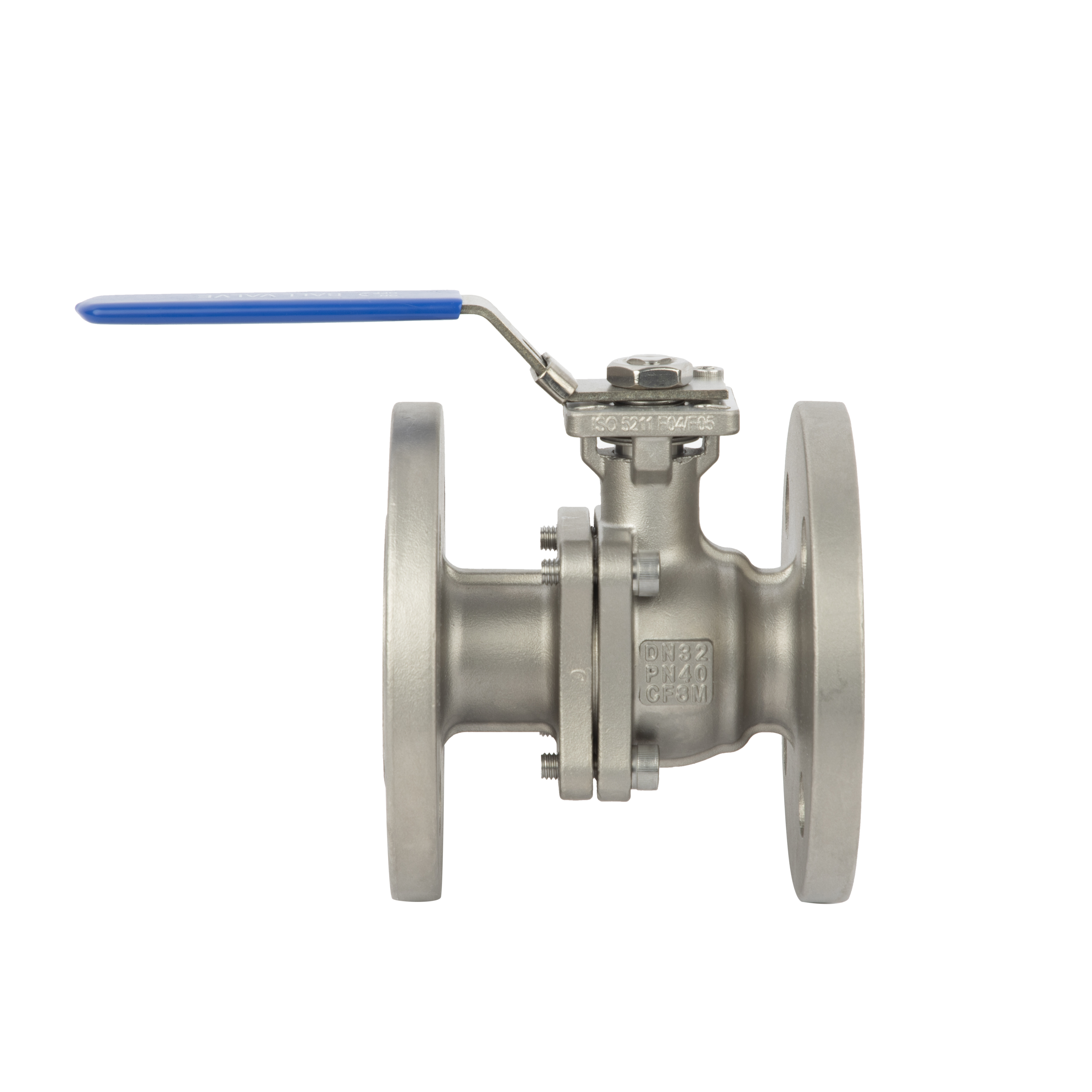
Dimensional standards dictate whether the valve physically fits into your piping spool. You verify face-to-face dimensions using ASME B16.10 or EN 558. If a replacement valve measures even a quarter-inch longer than the original, the pipe fitters cannot install it without cutting and re-welding the line. Regional standard mixing causes severe safety hazards. You cannot mate a JIS 20K flanged ball valve to an ASME B16.5 Class 150 or 300 pipe flange. The bolt circle diameters differ. The bolt hole counts often mismatch. Forcing bolts through misaligned holes creates uneven gasket compression, leading to immediate blowouts under pressure. You must verify the exact flange standard on the piping isometric drawings before issuing the purchase order.
Flange face types determine your sealing mechanism. Raised Face (RF) is the most common industrial standard. The raised section concentrates the bolt load onto a smaller gasket area, creating a tight seal. You pair these with spiral wound gaskets. Flat Face (FF) is used primarily when mating to brittle materials like cast iron or PVC. The flat surface distributes the bolt load evenly across the entire flange face, preventing the mating flange from cracking during torqueing. Ring Type Joint (RTJ) is reserved for high-pressure systems (Class 600 and above). The flange features a machined groove that accepts a metal ring gasket. As you tighten the bolts, the metal ring crushes into the groove, forming a high-integrity metal-to-metal seal.
Flange Face Type | Standard Application | Compatible Gasket | Bolt Torque Requirement |
|---|---|---|---|
Raised Face (RF) | Standard industrial piping (Class 150/300) | Spiral wound, PTFE envelope | High concentrated torque |
Flat Face (FF) | Cast iron, PVC, low-pressure water | Full face elastomer, EPDM | Low, evenly distributed torque |
Ring Type Joint (RTJ) | High pressure (Class 600+), offshore | Soft iron or stainless steel ring | Extreme torque for metal deformation |
Factory testing acts as your final barrier against field failures. You define strict acceptance criteria in your procurement documents. Do not rely on generic manufacturer promises. You mandate testing according to API 598 or API 6D. The hydrostatic shell test requires filling the open valve with water and pressurizing it to 150% of the maximum cold working pressure. The body casting must show zero sweating, weeping, or structural deformation. Next, they perform a high-pressure hydrostatic seat test at 110% of the design pressure, followed by a low-pressure pneumatic seat test at 80 psi. For soft-seated valves utilizing PTFE or PEEK, the acceptance criteria is zero visible leakage. If a single bubble escapes past the ball during the air test, the valve fails.
When dealing with high-pressure or hazardous media, standard hydrostatic testing is not enough. You mandate Non-Destructive Examination (NDE) on the valve castings. Radiographic Testing (RT), commonly known as X-ray, reveals internal shrinkage, porosity, or sand inclusions hidden beneath the surface of the steel. Magnetic Particle Inspection (MPI) or Dye Penetrant Inspection (DPI) detects microscopic surface cracks that could propagate under thermal stress. You specify these NDE requirements for any valve entering lethal service or high-pressure steam applications. The manufacturer must provide the NDE reports alongside the Material Test Reports.
Valves frequently pass factory tests but fail upon installation. Transit damage accounts for many of these issues. You require the manufacturer to install heavy-duty plastic or wood flange protectors before shipping. A single deep scratch across a raised face flange creates an unsealable leak path. Implement a strict visual and physical inspection protocol upon arrival at your receiving dock:
Remove the flange protectors and inspect the sealing faces for gouges, dents, or transit damage.
Verify the heat numbers stamped on the valve body match the provided Material Test Reports exactly.
Check the nameplate to confirm the pressure class, body material, and seat material align with the purchase order.
Shine a flashlight into the valve bore. Look for machining chips, blasting sand, or dust.
Never cycle the valve open and closed if you see debris inside. The foreign particles will score the ball and shred the soft PTFE seats instantly.
Clean the bore with compressed air before handing the valve over to the piping crew.
Auditing your flange ball valve manufacturer ensures you receive consistent, repeatable quality. You separate actual factories from trading companies by examining their infrastructure. A legitimate factory operates in-house CNC machining centers and dedicated pressure testing bays. They control the tolerances. Trading companies outsource the casting and machining to the lowest bidder, resulting in inconsistent wall thicknesses and poor stem finishes. You request their ISO 9001 certificate and verify their CE/PED compliance for European deployments. Ask for a virtual tour of their pressure testing bays to confirm they actually own the equipment required to execute API 598 protocols.
Documentation proves the material composition. You demand EN 10204 3.1 Material Test Reports (MTRs) for every pressure-containing component. The MTR lists the exact chemical breakdown and mechanical yield strength of the steel poured for your specific batch. If a supplier hesitates to provide an MTR, you reject the shipment. You also require the factory pressure test certificates and detailed installation manuals. Without these documents, you assume all liability for material failures in the field.
Lifecycle maintenance capabilities separate disposable valves from long-term assets. You review the manufacturer's preventative care guidelines. For larger valves or high-cycle applications, you verify the presence of external lubrication ports. These grease fittings allow your maintenance team to inject sealant directly into the seat pockets or stem packing area, stopping minor leaks without shutting down the process line. You also confirm the supplier maintains a deep inventory of spare parts. You need guaranteed access to replacement seats, thrust washers, and packing rings five years after the initial installation.
Proper installation dictates the lifespan of the valve. You instruct your pipe fitters to follow a rigid sequence to prevent mechanical binding and flange leaks.
Align the piping perfectly before lifting the valve into place. You never use the flange bolts to pull misaligned pipes together. This introduces severe bending stress into the valve body, which binds the ball and causes the stem to leak.
Leave the valve in the fully open position during installation. This protects the exposed surface of the ball from accidental tool strikes and keeps the seats fully supported.
Lubricate the flange bolts and tighten them in a crisscross star pattern.
Apply 30% of the final torque to all bolts, then 60%, and finally 100%. This guarantees parallel closure of the flange faces and uniform gasket compression.
Draft a comprehensive Request for Quotation (RFQ) that explicitly states the required pressure classes, body materials, and flange standards.
Mandate ISO 5211 mounting pad compatibility on all valve orders to ensure seamless integration with future pneumatic or electric actuators.
Write API 598 hydrostatic and pneumatic testing requirements directly into your purchase contracts to establish clear factory acceptance criteria.
Implement a mandatory receiving protocol that cross-references the physical heat numbers on the valve bodies with the provided EN 10204 3.1 Material Test Reports before installation.
A: The primary difference is the pressure-temperature rating and physical dimensions. An ASME 150LB valve handles lower pressures (up to 285 psi at ambient). A 300LB valve features thicker body walls, a larger bolt circle, and handles up to 740 psi. You cannot interchange them because their flange thicknesses and bolt-hole configurations defined by ASME B16.5 do not match.
A: No. JIS and ASME standards use completely different dimensional benchmarks. The bolt circle diameters and hole spacing do not align. Attempting to bolt a JIS valve to an ASME pipe flange is unsafe, prevents proper gasket compression, and leads to immediate mechanical failure or severe leaks. You must use matching standards.
A: A 2-piece design allows for a full-port configuration, eliminating flow restriction and pressure drops. More importantly, it provides maintenance access. You can unbolt the body halves to replace worn seats and seals without cutting the entire valve out of the piping system. One-piece valves are typically reduced-port and unrepairable.
A: You verify quality by demanding an EN 10204 3.1 Material Test Report (MTR) from the manufacturer. This document proves the exact chemical composition and yield strength of the steel casting. You also require API 598 pressure test certificates to confirm the valve passed hydrostatic shell and pneumatic seat leak tests.
A: Your purchase order must mandate a hydrostatic shell test at 1.5 times the rated design pressure and a seat leak test at 1.1 times the design pressure. For soft-seated valves, you must specify that zero visible leakage is allowed. Require the manufacturer to provide signed test certificates before shipping.
A: Field failures usually stem from installation errors or transit damage. Common causes include welding slag or dirt left in the pipeline that destroys the soft seats upon the first actuation. Improper bolt torque sequences can warp the flange, and transit damage to the raised face can prevent the gasket from sealing.
A: Face-to-face dimensions are governed by standards like ASME B16.10 or EN 558. These standards dictate the exact overall length of the valve body. This ensures that valves from different manufacturers are dimensionally interchangeable, allowing you to drop a new valve into an existing piping spool without modifying the pipe length.


