
Views: 0 Author: Site Editor Publish Time: 2026-10-07 Origin: Site


Backflow in hygienic processing lines causes immediate operational failures. Reverse flow leads to cross-contamination, batch spoilage, and severe pump damage from water hammer. Standard industrial valves fail in these applications because their internal mechanisms create dead legs that harbor bacteria. High-purity environments demand strict backflow prevention to guarantee unidirectional flow. You need a solution that never compromises Clean-in-Place (CIP) or Sterilize-in-Place (SIP) protocols while protecting sensitive downstream equipment like filtration membranes and optical sensors.
Selecting the correct valve requires evaluating fluid viscosity, line pressure, chemical compatibility, and connection types. This balances flow efficiency with strict regulatory compliance. A properly specified sanitary check valve ensures continuous production without risking product integrity. Plant engineers must match the internal valve mechanics to the specific media flowing through the pipeline to prevent premature wear and maintain sanitary conditions.
Sanitary check valves utilize pressure differentials to automatically seal against reverse flow, protecting upstream equipment, preventing system disruption, and maintaining product integrity.
Valve selection hinges on fluid characteristics: spring-assisted designs suit low-viscosity fluids, while Y-ball configurations are necessary for particulates and high-viscosity media.
Connection methods (weld end vs. union/clamp) dictate maintenance schedules, balancing permanent leak prevention against ease of teardown for Clean-Out-of-Place (COP) procedures.
Partnering with a certified sanitary check valve supplier ensures material traceability (MTRs) and compliance with 3-A, FDA, and USP Class VI standards.
Processing lines experience vulnerability during routine pump shutdowns, power failures, or sudden pressure drops. When a transfer pump stops, the fluid column in vertical piping naturally wants to drop back down due to gravity. If a municipal water tie-in experiences a pressure drop, it can pull process fluid backward through the system. This creates back-siphonage or back-pressure. Fluid moves backward through the piping network, threatening the entire production batch. It forces contaminated media or cleaning chemicals into clean zones. You must stop this movement before it breaches critical system boundaries.
Forward fluid pressure pushes against the internal resistance of the valve. This resistance is known as the cracking pressure. Once the fluid pressure exceeds this threshold, the internal mechanism moves out of the way, and the valve opens. The flow path remains clear as long as the forward pressure stays consistent. The internal mechanism holds its position against the flowing media. This ensures optimal flow velocity while minimizing the pressure drop across the pipeline network.
Instantaneous closure prevents disaster when forward pressure drops. The internal mechanism reacts immediately to changes in flow dynamics. A disc, ball, or piston forces itself against the valve seat. This creates a hermetic seal before backflow actually occurs. The speed of this closure dictates the safety of the system. Slow closure allows reverse flow to gain momentum, which eventually slams the valve shut and causes destructive water hammer. Fast closure stops the fluid column dead in its tracks, protecting upstream pumps and heat exchangers.
System-wide protection relies on this rapid sealing action. You prevent cross-contamination between raw product lines and caustic CIP chemical return lines. A single backflow event can force cleaning acids into finished beverage tanks. This ruins the product and forces costly facility-wide shutdowns for complete system flushing and re-sterilization. Reliable backflow prevention isolates these zones permanently, ensuring that raw materials, finished products, and cleaning agents never mix.
Sanitary design distinctions separate these components from standard utility valves used in HVAC or basic water transport. A hygienic valve requires 316L stainless steel construction for all wetted parts. The internal surface finish must meet strict roughness averages, typically requiring an Ra of less than 32 µin. Manufacturers electropolish these surfaces to eliminate microscopic crevices. Bacteria cannot hide on smooth surfaces. The design also eliminates internal threads in the product contact zone, ensuring complete sterilization during routine cleaning cycles.
A sanitary spring check valve uses a tensioned spring to control flow. The spring-loaded concentric disc compresses under forward pressure, allowing fluid to move past the disc smoothly. When pressure equalizes or drops, the spring snaps the disc shut against the elastomer seat. This happens before gravity can pull the fluid backward. The mechanical assist ensures a tight seal regardless of whether you install the valve vertically or horizontally.
These valves handle specific applications exceptionally well. Use them for reverse osmosis water, CIP fluids, beer, milk, and other low-viscosity media. They provide rapid closure to prevent water hammer. The spring action stops the fluid column instantly, protecting expensive positive displacement pumps and delicate flow meters upstream. You gain reliable performance in high-speed processing environments where rapid cycling is common.
Spring mechanisms have distinct limitations in the field. They fail when introduced to heavy particulates or highly viscous fluids. Sticky media like fruit slurries or Greek yogurt can foul the spring mechanism, preventing the disc from seating properly. This leads to slow closure, potential leak paths, and trapped product that survives the CIP cycle. You must match the valve type to the fluid characteristics carefully to avoid these mechanical failures.
A sanitary Y ball check valve features a unique Y-shaped body design. Forward flow pushes a heavy, elastomer-coated ball up into a side branch. The main flow path remains nearly unobstructed. During reverse flow, the ball drops back into the seat. Gravity or backpressure forces the ball into the sealing ring. This creates a tight closure without relying on delicate internal springs that can trap debris.
This design excels in challenging applications involving thick media. It handles slurries, liquid eggs, cosmetics, and fluids with suspended solids easily. The unobstructed path prevents clogs. Particulates pass through without snagging on internal guide stems or springs. You achieve minimal pressure drop across the system, which improves overall pumping efficiency and reduces energy consumption at the motor.
Installation orientation dictates the performance of this valve type. The mechanism relies heavily on gravity to seat the ball. You must install it vertically with upward flow, or at specific horizontal angles where the Y-branch points upward. Incorrect orientation prevents the ball from dropping into the seat correctly. This allows backflow to bypass the seal entirely. Always verify the manufacturer's installation guidelines before welding or clamping the valve into the piping matrix.
Some environments demand fail-safe backflow prevention. You achieve this by installing two separate check valves in series along the same pipeline. This dual configuration provides critical redundancy. If the primary valve fails due to particulate fouling or elastomer degradation, the secondary valve catches the reverse flow. The system remains protected under all circumstances.
Ultra-high-purity applications require this setup. Water for Injection (WFI) systems in pharmaceutical plants mandate absolute redundancy to prevent contamination of the water loop. You also use dual configurations when isolating harsh chemical processing systems from municipal water supplies. Regulatory bodies often require this level of protection to guarantee that toxic chemicals never reach public water infrastructure during a massive pressure loss event.
Integrating valves directly into the pipeline requires precision and planning. A sanitary weld end check valve permanently joins the piping system. Installers use orbital welding equipment to ensure a smooth, crevice-free transition between the pipe ferrule and the valve body. They purge the inside of the pipe with argon gas during the weld to prevent oxidation and sugaring on the internal weld root. This creates a continuous flow path without mechanical joints.
The permanent nature offers distinct operational advantages. It eliminates gasket degradation risks entirely at the connection points. You achieve a zero-leak path. This setup handles continuous, high-pressure SIP systems perfectly. High steam temperatures cause thermal expansion that can loosen mechanical clamps, but welded connections remain secure. You reduce long-term maintenance costs associated with replacing worn external elastomer seals.
Permanent installation presents maintenance challenges. You cannot easily remove the valve for manual inspection or swabbing. The system requires strict reliance on CIP efficacy to clean the internal components. If a particulate fouls the internal mechanism, you must cut the valve out of the line using a pipe saw, repair it, and re-weld it. Installation demands high-level orbital welding expertise to prevent internal weld slag from creating a breeding ground for bacteria.
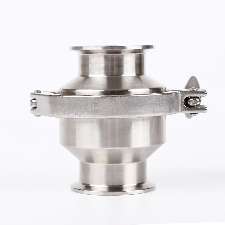
Modular installation provides operational flexibility for facilities that change product lines frequently. A sanitary union type check valve uses threaded unions or Tri-Clamp fittings. You secure the valve between two pipe ferrules using a specialized gasket and a mechanical clamp. This creates a hygienic seal that operators can assemble and disassemble rapidly using basic hand tools.
This flexibility facilitates rapid teardown. Operators perform Clean-Out-of-Place (COP) procedures easily by dropping the valve out of the line and placing it in a wash tank. You can conduct routine internal elastomer replacement without cutting pipe. Line reconfiguration becomes simple. If production needs change, you unclamp the valve and move it to a new location in minutes.
Mechanical joints introduce potential risks to the processing line. They create potential leak points at the gasket interfaces. Operators must practice strict torque management when tightening the clamps. Over-tightening causes the gasket to extrude into the product stream, creating a dead leg where bacteria multiply. Under-tightening leads to external leaks, pressure loss, and potential air ingress into the product line.
Comparison of Sanitary Check Valve Connection Types | ||
Feature | Weld End Connection | Union / Tri-Clamp Connection |
|---|---|---|
Installation Method | Permanent orbital welding with argon purge | Mechanical clamp and sanitary gasket |
Leak Risk at Connection | Zero (no external gaskets involved) | Moderate (depends on gasket integrity and torque) |
Maintenance Access | Requires cutting the pipeline with a saw | Rapid teardown for COP and inspection |
Best Application | High-pressure, continuous SIP lines | Frequent inspection and line reconfiguration |
Thermal Shock Resistance | Excellent (handles extreme steam cycles) | Good (clamps may require re-torquing after SIP) |
Tooling Required | Orbital welder, facing tool, purge gas | Standard wrenches or hand-tightening |
Calculating the correct pressure drop prevents system failure and pump damage. You must match the valve's flow coefficient (Cv value) to the pump's output. The Cv value indicates the volume of water (in gallons per minute) that passes through the valve at a one PSI pressure drop. An undersized valve restricts flow severely. This forces the pump to work harder to push fluid through the narrow opening. It eventually causes cavitation, destroying pump impellers and generating metallic debris that contaminates the product.
Mitigating water hammer requires precise engineering and component selection. A properly specified sanitary processing line check valve prevents hydraulic shock. When a pump shuts off, the fluid column reverses rapidly. If the valve closes too late, the returning fluid slams into the closed disc. This sends a destructive shockwave through the piping, rupturing gaskets and damaging heat exchanger plates. Selecting the correct cracking pressure and closure speed stops the fluid before reverse momentum builds.
CIP and SIP drainability risks demand careful installation practices. You must install valves at self-draining angles. A valve installed perfectly horizontal might pool fluid in the body cavity. This pooled fluid survives the CIP cycle and becomes a contamination vector for the next production batch. Always pitch horizontal lines slightly (typically 1/8 inch per foot) to ensure complete gravity drainage. Use eccentric reducers if pipe sizes change near the valve to prevent pooling at the transition points.
Elastomer compatibility in chemical systems dictates seal longevity. Harsh cleaning chemicals degrade standard rubber quickly, leading to leaks and product contamination. You must match the seat materials to the specific processing temperatures and chemical agents used in your facility.
EPDM: Handles steam and hot water exceptionally well. It resists standard CIP acids but fails quickly when exposed to oils or fatty dairy products.
FKM (Viton): Resists harsh acids and ozone. It handles high temperatures but struggles with extreme cold and prolonged steam exposure.
PTFE (Teflon): Offers the broadest chemical resistance available. It withstands almost all CIP chemicals but lacks elasticity, requiring higher seating force to create a tight seal.
Silicone: Works well for high temperatures and maintains flexibility in cold applications. However, it tears easily and does not withstand abrasive slurries.
Material traceability ensures regulatory compliance and system longevity. You must demand Material Test Reports (MTRs) for all wetted stainless steel components. These documents prove the exact chemical composition of the metal, including the heat numbers stamped on the valve body. They verify that the 316L stainless steel meets industry standards for chromium and molybdenum content. Without MTRs, you risk installing substandard alloys that corrode under harsh CIP chemicals, leading to rouge formation and product contamination.
Customization capabilities separate standard vendors from true engineering partners. A reliable supplier modifies valves to match specific line dynamics. They provide custom cracking pressures by altering the internal spring tension. If your low-pressure transfer system cannot open a standard valve, the supplier must offer a lighter spring. This prevents flow restriction while maintaining backflow security. They should also offer various surface finish options, including mechanical polishing and electropolishing, to meet your specific Ra requirements.
Compliance verification protects your facility from audit failures and forced shutdowns. Ensure your sanitary check valve supplier provides documented proof of adherence to industry standards. Look for 3-A Sanitary Standards authorization, which confirms the design is hygienic and cleanable. Verify FDA CFR Title 21 (specifically 177.2600) compliance for all elastomer seals to ensure they are safe for food contact. Require USP Class VI certifications for pharmaceutical applications to guarantee the elastomers do not leach toxins into the product.
Preventing backflow and equipment damage in hygienic lines requires precision engineering and careful component selection. You must match valve mechanics, fluid viscosity, and cleaning protocols perfectly. A mismatched valve causes contamination, pump destruction, and audit failures. Proper specification ensures continuous, safe production while protecting your most expensive downstream assets.
Follow a strict shortlisting logic when designing your piping system. Default to spring check valves for low-viscosity fluids and high-speed closure requirements. Choose Y-ball configurations for heavy particulates, slurries, and viscous media. Specify weld ends for permanent, high-pressure SIP lines where leak prevention is paramount. Utilize union or clamp types for systems requiring frequent manual inspection, line reconfiguration, and COP.
Take these action steps to secure your processing lines:
Conduct a comprehensive line pressure audit to determine your exact cracking pressure requirements for each piping zone.
Calculate the required Cv values for your specific pump outputs to prevent flow restriction and cavitation.
Evaluate your current CIP chemical concentrations and temperatures to select the correct elastomer seat materials.
Audit your existing piping layout to ensure proper self-draining angles for all horizontal valve installations.
Request complete MTR documentation, FDA certificates, and 3-A authorization from shortlisted suppliers before finalizing procurement.
A: Standard cracking pressures typically range from 0.5 to 2.0 PSI. This low resistance allows forward flow to open the valve easily without overworking the pump. Manufacturers customize this pressure by modifying the internal spring tension. Higher cracking pressures are available for vertical installations where the fluid must overcome gravity before opening the flow path.
A: Yes, but with strict limitations. A Y ball check valve relies on gravity to seat the ball during reverse flow. If installed horizontally, the Y-branch must point upward at a specific angle dictated by the manufacturer. Incorrect horizontal orientation prevents the ball from dropping into the seat, causing the valve to fail.
A: Dual configurations are required for ultra-high-purity applications, such as Water for Injection (WFI) systems. They are also mandatory when isolating harsh chemical processing systems from municipal water supplies. This series installation provides absolute fail-safe redundancy. If one valve fails due to particulate fouling, the second valve guarantees backflow prevention.
A: Replacement schedules depend entirely on CIP frequency, chemical harshness, and operating temperatures. High-temperature SIP cycles and caustic acids degrade elastomers faster. Inspect seals monthly during routine COP. Replace them immediately if you notice hardening, swelling, or cracking. Most facilities implement a standard quarterly or bi-annual preventative replacement schedule.
A: Valve chatter occurs when the forward flow velocity is insufficient to keep the internal mechanism fully open. The disc or ball bounces rapidly against the seat. This is usually caused by installing an oversized valve for the pump's output. Chatter causes premature wear on the internal components and generates metallic debris.
A: Ensure the CIP flow velocity exceeds 5 feet per second to create sufficient turbulence inside the valve body. You must also install the valve at a self-draining angle. Horizontal lines should have a slight pitch (typically 1/8 inch per foot). This prevents cleaning fluids from pooling inside the valve body after the cycle completes.
A: A certified supplier must provide Material Test Reports (MTRs) for all wetted stainless steel components, linking heat numbers to the metal's chemical composition. They should supply FDA CFR Title 21 compliance certificates for all elastomer seals. For pharmaceutical applications, require USP Class VI certification. Finally, look for official 3-A Sanitary Standards authorization documentation.


